You can use the MotorControl sketch for the Arduino to put some input into a DC motor to give you full control of the motor on the fly. Basic Arduino Code to control the motor to Start Stop and control the speed of your motor using Pulse Width Modulation PWM Parts List and Tools.
Contronling Dc Motor Speed

You cant drive a motor direct from an arduino pin you need a driver like a transistor.
Dc motor speed control arduino. In this project an Arduino based speed and direction control of DC motor without using Motor Driver IC is designed. A DC Motor cant be connected to a Microcontroller as the output current of the Microcontroller is very small and it cannot drive the motor. To control the speed feed the motor with a PWM signal you get it from an analogWrite function this only works with certain pins see your arduino model for which.
We can send the command to PC on the serial monitor. Resources for this sketch. Hence we use transistors to form an H-bridge to drive the motor.
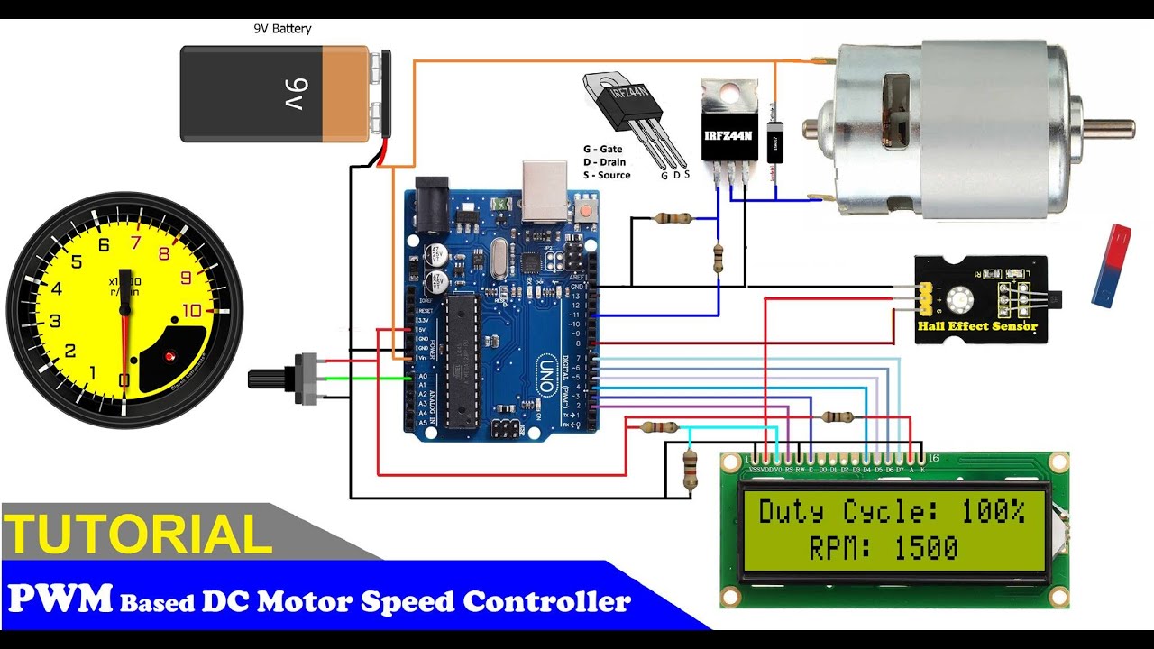
With the potentiometer you can achieve step-less speed control for the motor. 100K ohm potentiometer is connected to the analog input pin A0 of the Arduino UNO and the DC motor is connected to the 12 th pin of the Arduino which is the PWM pin. Speed Control of DC Motor using Arduino.
For information on PWM see-. The motor speed can be adjusted by adjusting the duty cycle of PWM. Connect an Arduino PWM output to the base of transistor or the gate of a MOSFET and control the speed of the motor by controlling the PWM output.
With these changes I can achieve speed control for my Arduino DC Motor project. 2 Connect the cathode of the red led to GNDPIN. In this tutorial we have study about DC Motor control forward direction or revere direction using RGB LED.
Arduino Ive used an Arduino Micro but any Arduino will suffice 12V or equivalent 5V DC Motor. 1 X USB Cable. The computer should have HMI made by Visual Studio to communicate with Arduino.
PWM pulse can be generated using Arduino and L298 Enable Pin is used to get that PWM pulse and then it controls the motor speed accordingly. The speed of the motor depends on value that was passed to the analogWrite function. To control the speed of the motor all we need to do is to replace digitalWrite function on L293D enable pins to analogWrite.
When the speed is varied from 1 to 9 the speed increases with the value 9 set as the maximum speed of the motor. Much like the name suggests DC motor controllers control the speed and direction of a DC motor. Its current rating is 2A for each motor.
Arduino varies speed of DC Motor using PWM and measures its RPM using optical sensor and displays them on LCD DC Motor speed control and measurement Project tutorial by ambhatt. Before going into the further details I would like to tell you about the concept of PWM for controlling DC motor. 1 DC motor.
If you pass 0 then the motor will stop and if you pass 255 then it will run at full speed. 1 Arduino UNO. This video shows you how to control DC motor speed with L293D motor driver and PWM using Arduino.
Selecting a IO port to connect the IN1 and IN2 pins through. We can change the speed of motor from 0 to 9. The L298 can control the speed and direction of DC motors and stepper motors and can control two motors simultaneously.
The working of Arduino program is very simple as it reads the voltage from the analog pin A0. Arduino is connected to PC through the USB cable. Controlling a DC Motor Controlling the speed of the DC motor Simply control the input voltage to the motor.
DC Motor Direction Control Arduino Mega Overview. Arduino DC Motor Control Working. The middle pin on the switch can be connected to ground while the right pin can be connected to Arduino Digital Pin 2 White in the diagram.
Speed control of any motor is always done y Pulse Width Modulation abbreviated as PWM. And to vary the DC motor speed a pulse-width modulation PWM signal or wave must be applied to it. In this circuit for controlling the speed of DC motor we use a 100K ohm potentiometer to change the duty cycle of the PWM signal.
To change the direction of the motor however the supply it receives must be reversed. At these currents however you will need to use heat sinks. First insert the breadboard friendly switch into the breadboard.
You will need the following components 1 L298 bridge IC. L293x Quadruple Half-H Drivers datasheetpdf. The potentiometer will be used to control the motor speed and a small switch will control the direction the motor spins.
The Arduino Pro Mini is used to store motor controls PID algorithms and to communicate with the PC through COM Port. 3 Connect a 220ohms resistor to the anode of the green led and connect the end of the resistor to DIGITALPIN9 on the arduino. Control DC motor using L293D motor driver with Aarduino PWM.
A PWM DC motor controller technology is used to control the speed. Remember the value can be between 0 and 255. Need more control of your DC motor.
Higher the voltage higher the speed of rotation of the motor. 1 x Arduino Mega 2560 R3. In PWM the Arduino sends a pulsating.
1 Connect a 220ohm or any ressitor below 1komhs to the anode of the red led and connect the end of the resistor to DIGITALPIN8 on the arduino. Code for L293D Motor shield to control 4 DC motor Is here. Test circuit with speed control In this test the circuit is basically the same as in the previous post but I decided to add a potentiometer to it.
HMI will show motor speed graphs and change motor speed settings. When 0 is sent over the Serial Monitor the motor runs at minimum speed that is zero.